
Two-Wire 10-Digit LED Module
January 2009
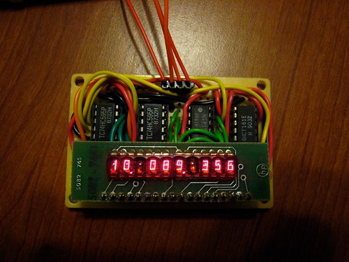
I got this old seven-segment LED display from HSC Electronic Supply. It's a circuit board with two five-digit modules soldered to it, and 18 holes for connections at the bottom. The part number is 5082-7451, it looks like it was made by Hewlett-Packard in the 1970s. It's the same red-bubble display that HP used in their early calculators, like the HP-35, the world's first pocket scientific calculator.
There's not a whole bunch of information about these on the internet. An old HP data book (yes, book) gave me some information. The two five-digit modules are common-cathode and have part number 5082-7415; a datasheet for the 5082-7433, a similar three-digit module, is here. However, I wound up figuring out the pinout myself with a diode tester. The pin designations are, from left to right:
Pin  Connection
---  ----------
1    Cathode 1
2    Anode C
3    Cathode 2
4    Anode dp
5    Cathode 3             A
6    Anode A             -----
7    Cathode 4          |     |
8    Anode E           F|     |B
9    Cathode 5          |  G  |
10   Anode D             -----
11   Cathode 6          |     |
12   Anode G           E|     |C
13   Cathode 7          |  D  |  dp
14   Anode B             -----   []
15   Cathode 8
16   Anode F
17   Cathode 9
18   Cathode 10
Using this display, I built some logic that allows the display to be driven with only two pins on a microcontroller. It uses a two-wire serial protocol with a 16-bit data word with the following format:
Bit: 0  1  2  3  4  5  6  7  8  9  10 11 12 13 14 15
----------------------------------------------------
     0  0  0  0  A3 A2 A1 A0 dp G  F  E  D  C  B  A
The first four bits are padding; the next four (A3..A0) indicate which digit to light up (only one digit at a time is illuminated, the microcontroller must multiplex the digits), and the last eight bits are the segment pattern.
The driver uses four ICs: two 74HC595 shift registers, a 74HC42 (or 74LS145) 1-of-10 decoder, and a 74HC161 4-bit counter. Data is loaded into the two cascaded shift registers on the rising edge of the clock pulse. The eight outputs of the lower shift register are connected to the segment anodes, and the four high outputs of the high shift register are connected to the inputs of the decoder. The ten decoder outputs are connected to the digit cathodes; the decoder's input (the 4 bits of the high shift register) indicate which output to drive low, and therefore, which digit to illuminate.
The clock pulse is also fed into a 4-bit counter. Every 16 pulses, the counter's most significant bit output transitions from low to high. This pin is connected to the strobe input of the shift registers; after 16 bits have been received, this low-to-high transition automatically causes the shift registers to update the state of the outputs with the new data. Note that, in order for this synchronization to work, the microcontroller must first send eight dummy clock pulses to the counter.
An RC circuit is connected to the counter's active-low clear pin to ensure that its count is always zero after power-on.
The display can now be connected to a microcontroller for debugging purposes or any situation when numeric output would be helpful. In the future I might use one of these displays to make a little clock; they really look awesome in person, very very red. My crap camera doesn't do them justice.
links/resources
photos
Photo gallery is on Flickr.schematic
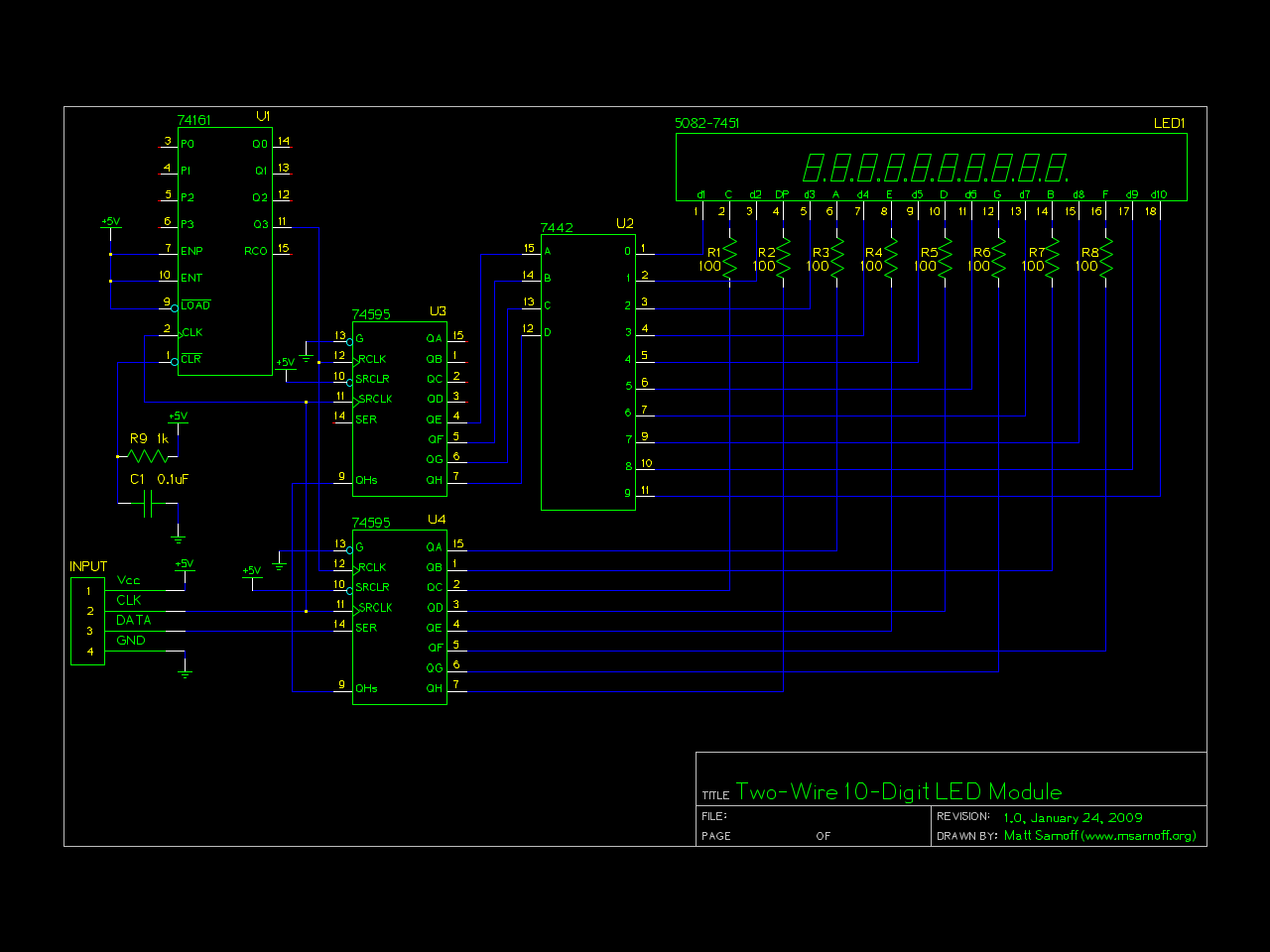
(click to enlarge)
Download gEDA schematic: leddisplay.sch
May require custom symbols from my symbols directory.